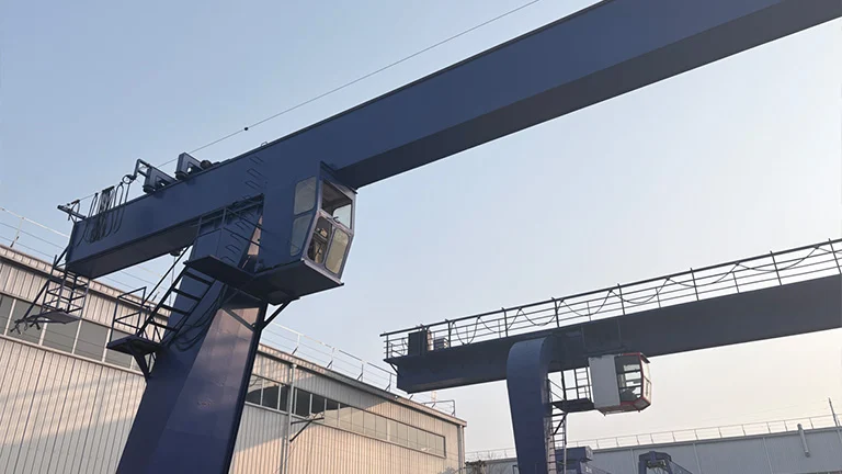
A geared motor is a power transmission device that integrates an electric motor with a gear reducer. The motor shaft is integrated with the first-stage gear shaft, resulting in a particularly compact structure. Its core function is to utilize the speed reduction and torque multiplication characteristics of the gear train to output low-speed, high-torque power that matches the operating conditions of the equipment. It is widely used in industrial applications such as cranes, conveyors, and automated production lines where precise control of speed and torque is required.
1.Working Principle of a Gear Motor
The electric motor outputs original power with high speed and low torque. After the power is transmitted to a reducer composed of multiple stages of meshing gears, the speed is reduced proportionally according to the preset reduction ratio through the speed and torque conversion characteristics between the gears, while the torque is simultaneously amplified. Finally, stable low-speed, high-torque power is output to meet the load-driving requirements of the equipment.
2.Classification of Gear Motors
According to different gearbox structures, geared motors can be classified into F-series parallel-shaft helical geared motors, K-series helical-bevel geared motors, R-series helical geared motors, etc. Different gearbox structures vary in terms of transmission characteristics, overall size, and applicable operating scenarios.
2.1 F-Series Parallel-Shaft Helical Geared Motor
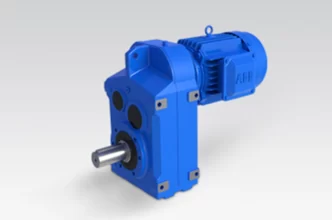
The F-series parallel-shaft helical geared motor adopts a parallel-shaft layout with a slim profile, thereby significantly saving installation space and making it particularly suitable for equipment with limited mounting space. At the same time, it features a modular design, which enables interchangeability with internationally renowned brands and ensures that only a small number of core spare parts are required for routine maintenance.
In addition, the geared motor provides highly flexible mounting options and can therefore be installed in any of six orientations. Specifically, supported mounting types include foot-mounted, flange-mounted, and torque arm mounting. Meanwhile, the output shaft is available in both solid and hollow versions, and can further be connected to the driven machine via a single key, splines, or a shrink disc, thus meeting the assembly requirements of a wide range of equipment types.
Technical Parameters Table:
| Size | 37 | 47 | 57 | 67 | 77 | 87 | 97 | 107 | 127 | 157 |
| Structure | F:Foot-mounted solid shaft;FA:Hollow shaft;FF:Flange-mounted solid shaft;FAF:Flange-mounted hollow shaft;FAZ:Short-flange-mounted hollow shaft | |||||||||
| Input rated power(KW) | 0.18~
3 |
0.18~
3 |
0.18~
5.5 |
0.18~
5.5 |
0.37~
11 |
0.75~
22 |
1.1~
30 |
2.2~
45 |
7.5~
90 |
11~
200 |
| Ratio | 3.81~
128.51 |
5.06~
189.39 |
5.18~
199.70 |
4.21~
228.99 |
4.30~
281.71 |
4.12~
270.68 |
4.68~
280.76 |
6.20~
254.40 |
4.63~
172.17 |
11.92~
267.43 |
| Permissible torque(N.m) | 200 | 400 | 600 | 820 | 1500 | 3000 | 4300 | 7840 | 12000 | 18000 |
2.2 K Series Helical-Bevel Geared Motors
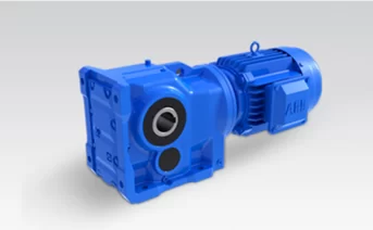
The K Series reducer motors employ a two-stage gear meshing design to achieve spatial power reversal. The high-speed stage utilizes helical gears, where the high-speed power input from the motor undergoes initial reduction through helical gear meshing while simultaneously reducing operational noise. The low-speed stage employs bevel gears with shaft axes offset at 90°, enabling power reversal transmission in both horizontal and vertical directions to meet equipment requirements for installation space and output orientation.
The motor, gearbox, and flange plate adopt a modular design, allowing selection of motors with different power ratings as needed. Output shaft configurations include solid shaft and hollow shaft options, supporting mounting types such as foot mounting, flange mounting, and torque arm mounting.
Technical Parameters Table:
| Size | 37 | 47 | 57 | 67 | 77 | 87 | 97 | 107 | 127 | 157 | 167 | 187 |
| Structure | K:Foot-mounted solid shaft;KA:Hollow shaft;KF:Flange-mounted solid shaft;KAF:Flange-mounted hollow shaft;KAT:Torque-arm-mounted hollow shaft;KAB:Foot-mounted hollow shaft | |||||||||||
| Input rated power(KW) | 0.18~3 | 0.18~3 | 0.18~5.5 | 0.18~5.5 | 0.37~11 | 0.75~22 | 1.1~
30 |
3~
45 |
7.5~90 | 11~160 | 11~200 | 18.5~200 |
| Ratio | 5.36~
106.38 |
5.81~
131.87 |
6.57~
145.14 |
7.14~
144.79 |
7.24~
192.18 |
7.19~
197.37 |
8.95~
176.05 |
8.74~
141.46 |
8.68~
146.07 |
12.65~
150.41 |
17.28~163.91 | 17.27~180.78 |
| Permissible torque(N.m) | 200 | 400 | 600 | 820 | 1550 | 2700 | 4300 | 8000 | 13000 | 18000 | 32000 | 50000 |
2.3 R Series Helical Gear Reducer Motor
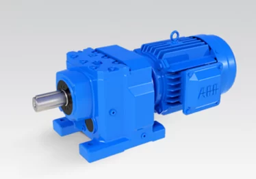
The R Series helical gear reducer motor is a general-purpose reduction drive unit with a coaxial structure, in which the input shaft and output shaft are aligned on the same central axis. This design enables a more direct power transmission path and a highly compact structure, allowing two-stage or three-stage reduction to be achieved within a limited installation space.
It adopts a high-precision helical gear transmission design, with the motor and reducer integrated into one unit. Speed reduction and torque increase are realized through multi-stage helical gear meshing, ensuring stable output speed and smooth transmission.Available mounting options include foot mounting, flange mounting, and other configurations.
Technical Parameters Table:
| Size | 17 | 27 | 37 | 47 | 57 | 67 | 77 | 87 | 97 | 107 | 137 | 147 | 167 |
| Structure | R:Foot-mounted;RF:Flange-mountedt; | ||||||||||||
| Input rated power(KW) | 0.18~0.75 | 0.18~3 | 0.18~3 | 0.18~5.5 | 0.18~7.5 | 0.18~7.5 | 0.18~
11 |
0.55~
22 |
0.55~30 | 2.2~45 | 5.5~55 | 11~90 | 11~160 |
| Ratio | 3.83~
74.84 |
3.37~
135.09 |
3.33~
134.82 |
3.83~
176.88 |
4.39~
186.89 |
4.29~
199.81 |
5.21~
195.24 |
5.36~
246.54 |
4.49~
289.74 |
5.06~
249.16 |
5.15~
222.60 |
5~
163.31 |
10.24~
229.71 |
| Permissible torque(N.m) | 85 | 130 | 200 | 300 | 450 | 600 | 820 | 1550 | 3000 | 4300 | 8000 | 13000 | 18000 |
| Size | 37 | 57 | 67 | 77 | 87 | 97 | 107 | 127 | 157 | |
| Structure | RX:Foot-mounted with shaft input;RXF:Flange-mounted with shaft input; | |||||||||
| Input rated power(KW) | 0.18~1.1 | 0.18~5.5 | 0.18~7.5 | 1.1~11 | 3~22 | 5.5~30 | 7.5~
45 |
7.5~
90 |
11~132 | |
| Ratio | 1.62~
4.43 |
1.3~
5.5 |
1.4~
6.07 |
1.42~
8 |
1.39~
8.65 |
1.42~
8.23 |
1.44~
6.63 |
1.51~
6.2 |
1.57~
6.2 |
|
| Permissible torque(N.m)) | 20 | 70 | 135 | 215 | 400 | 600 | 830 | 1110 | 1680 | |
3.Core Advantages of Gear Motors
3.1 Integrated Design:
The motor and gearbox are integrated into a single unit, featuring a compact size and easy installation. This reduces the space requirement and cost associated with separately configuring a reducer.
3.2 High Torque and Controllable Speed:
By adjusting the reduction ratio, the gear motor can precisely match the speed and torque requirements of different equipment.
3.3 Stable Operation:
The mechanical characteristics of gear meshing transmission ensure smooth power output and strong overload capacity, making it well suited for heavy-duty industrial operating conditions.
3.4 Low Maintenance Cost:
The sealed design minimizes the ingress of dust and oil contamination, extending service life and reducing maintenance requirements.
4.Application Scenarios of Gear Motors
4.1 F Series:
The F Series adopts a parallel-shaft helical gear transmission, where the input shaft and output shaft are parallel but not coaxial. Speed reduction is achieved through multiple sets of parallel-arranged helical gears. Proper shaft parallelism and positioning accuracy are required to ensure stable transmission. This design offers a more balanced use of lateral space and is well suited for integration into equipment that requires horizontal power transmission.
4.2 K Series:
The K Series features a combined transmission structure of helical gears and bevel gears, enabling right-angle output. This special configuration changes the direction of power transmission, addressing applications where the power source and the driven component are arranged vertically. The precision-machined gear train ensures both stable power transmission and reliable direction change.
4.3 R Series:
The R Series is based on a coaxial helical gear transmission, with the input shaft and output shaft aligned on the same central axis. This structure provides a more direct power transmission path and a highly compact design, allowing two-stage or three-stage reduction within a limited space. However, the axial length is relatively larger, which imposes certain constraints on shaft positioning during equipment layout.
5.Key Selection Parameters for Gear Motors
5.1 Rated Power:
The required rated power of the gear motor should be calculated based on the load of the driven machine and the required operating speed.
5.2 Reduction Ratio:
The reduction ratio determines the output speed and torque and should be calculated according to equipment requirements(Reduction ratio = Input speed / Output speed).
5.3 Rated Torque:
The rated torque must be greater than the load torque of the equipment, with a safety factor of 1.2–1.5 times reserved.
5.4 Mounting Method:
Common mounting methods include foot mounting, flange mounting, shaft-mounted, and torque arm types, which should be selected to match the available installation space of the equipment.
5.5 Ambient Temperature:
For normal ambient temperatures (–10°C to 40°C), standard gear motor models with cast iron housings are suitable. In contrast, for high-temperature environments (40°C to 120°C), models equipped with high-temperature-resistant seals are required. Similarly, under low-temperature conditions (–30°C to 0°C), the use of cold-resistant lubricants becomes essential. Moreover, in dusty or humid environments, gear motors with IP54 or IP65 protection ratings are strongly recommended. For food-processing applications, stainless steel housings combined with food-grade lubricants are necessary to meet hygiene and safety standards.
Building on these application requirements, Hanko Heavy Industry gear motors integrate the complete R, F, and K series product portfolio, with high-precision ground gear technology and heavy-duty transmission design at their core. As a result, they cover a full range of application scenarios, including coaxial, parallel-shaft, and right-angle drives. Notably, with a maximum transmission efficiency of up to 96% and peak torque output exceeding 50,000 N·m, these gear motors are well suited for demanding heavy-load conditions such as cranes, mining equipment, and special-purpose vehicles.
Furthermore, the integrated cast iron housing, combined with high-quality forged steel gears strengthened by high-frequency heat treatment, delivers excellent wear resistance and impact resistance, while protection ratings up to IP65 ensure reliable operation in harsh environments. Thanks to the modular mounting design, the gear motors flexibly support foot mounting, flange mounting, torque arm installation, and other multi-position configurations, thereby providing powerful and reliable transmission support for stable equipment operation.
Choose Hanko gear motors — efficient power transmission with reliability you can trust.