
When you design or select a crane drum, you need to understand how drum dimensions affect rope capacity, spooling behavior, and structural integrity. This guide covers the standard dimension ranges, groove specifications, and calculation methods for wire rope drums used in overhead, gantry, and portal cranes.
Featured Snippet: Quick Answer
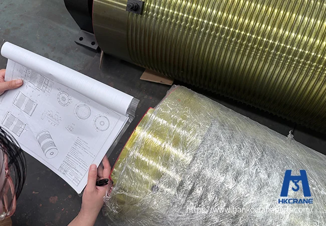
Standard crane drum dimensions include drum diameter (10–25× the rope diameter), groove pitch (rope diameter + 1–3 mm tolerance), barrel length (based on rope capacity and spooling layers), and shell thickness (calculated from rope tension and drum material). A Lebus groove pattern is used for multi-layer spooling to prevent rope crowding and cross-overs. All dimensions should be verified against FEM, DIN 15061, or ISO standards.
Key Crane Drum Dimensions
Drum Barrel Diameter (D)
The drum barrel diameter is the outer diameter of the drum’s rope-bearing surface. It is the most critical dimension because it directly affects rope fatigue life.
| Drum Diameter Ratio (D/d) | Приложение | Typical Rope Diameter (d) | Drum Diameter (D) |
|---|---|---|---|
| 25–30 | Heavy-duty, frequent operation | 16–24 mm | 400–720 mm |
| 20–25 | Standard industrial cranes | 12–20 mm | 240–500 mm |
| 16–20 | Light-duty, occasional use | 8–14 mm | 128–280 mm |
| 12–16 | Mobile or temporary cranes | 6–10 mm | 72–160 mm |
The D/d ratio is governed by your crane’s duty class. When you choose a higher ratio, you extend rope life by reducing bending stress. For permanent overhead and gantry cranes, FEM 1.001 recommends D/d ≥ 20 for M5 duty class and D/d ≥ 25 for M7–M8.
Groove Pitch (t)
The groove pitch is the center-to-center distance between adjacent rope grooves. You must ensure it accommodates your rope diameter with sufficient clearance to prevent friction between adjacent wraps.
| Rope Diameter d (mm) | Groove Pitch t (mm) | Groove Depth h (mm) |
|---|---|---|
| 8 | 9.0–9.5 | 4.0–4.5 |
| 10 | 11.0–11.5 | 5.0–5.5 |
| 12 | 13.0–13.5 | 6.0–6.5 |
| 14 | 15.5–16.0 | 7.0–7.5 |
| 16 | 17.5–18.0 | 8.0–8.5 |
| 18 | 20.0–20.5 | 9.0–9.5 |
| 20 | 22.0–22.5 | 10.0–10.5 |
| 24 | 26.5–27.0 | 12.0–12.5 |
| 28 | 31.0–31.5 | 14.0–14.5 |
| 32 | 35.5–36.0 | 16.0–16.5 |
Groove pitch follows DIN 15061 and ISO 8085 standards. The standard tolerance for machined grooves is ±0.3 mm on pitch. For more on groove specifications and machining tolerances, see our crane drum design guide.
Drum Barrel Length (L)
The barrel length is the working rope-winding length, excluding the end flanges. It is calculated based on the total rope capacity required and the number of spooling layers.
Single-layer calculation:
Working length L = (Number of wraps) × groove pitch t

Number of wraps = Total rope length / (π × D)
Multi-layer calculation (2 layers):
Effective diameter per layer:
  Layer 1: D₁ = D
  Layer 2: D₂ = D + 2 × (d + 0.5 × clearance)

Total rope capacity = Σ(π × Dₙ × wraps per layer)
For multi-layer drums, you should strongly consider a Lebus groove pattern. The Lebus system uses a parallel groove section and a cross-over zone that guides the rope from one layer to the next without crushing or cutting into the underlying wraps. If you use 3 or more layers, this is critical, as discussed in our wire rope drum design article.
Shell Thickness (δ)
Your drum shell must withstand the compressive stress from the rope’s winding force. You can calculate the minimum shell thickness from the rope tension and allowable compressive stress of the drum material.
Calculation formula (simplified):
δ ≥ (S × t) / (L × σ_allowable)

Where:
  δ  = shell thickness (mm)
  S  = maximum rope tension (N)
  t  = groove pitch (mm)
  L  = effective barrel length between end plates (mm)
  σ_allowable = allowable compressive stress of drum material (MPa)
| Drum Material | Allowable Compressible Stress (MPa) | Typical Shell Thickness Range |
|---|---|---|
| Cast iron (HT200) | 80–100 | 18–40 mm |
| Cast steel (ZG230-450) | 120–140 | 14–32 mm |
| Welded steel (Q235B) | 140–160 | 12–28 mm |
| Welded steel (Q345B) | 160–180 | 10–25 mm |
Cast drums are common for standard applications, while you should prefer welded steel drums for heavy-duty or custom-sized applications. For a comparison of manufacturing methods, see our crane drum selection guide.
Flange Diameter (Df)
End flanges prevent the rope from sliding off the drum. You must ensure the flange diameter exceeds the outermost rope layer diameter by at least 2–2.5 rope diameters.
Df ≥ D_outermost_layer + (2 to 2.5) × d
For a single-layer drum with 20 mm rope and D = 500 mm:
Df ≥ 500 + (2.5 × 20) = 550 mm
For a 3-layer drum, the outermost layer diameter would be D + 5d (approximately), so:
Df ≥ (D + 5d) + 2.5d
Drum Bore and Journal Diameter
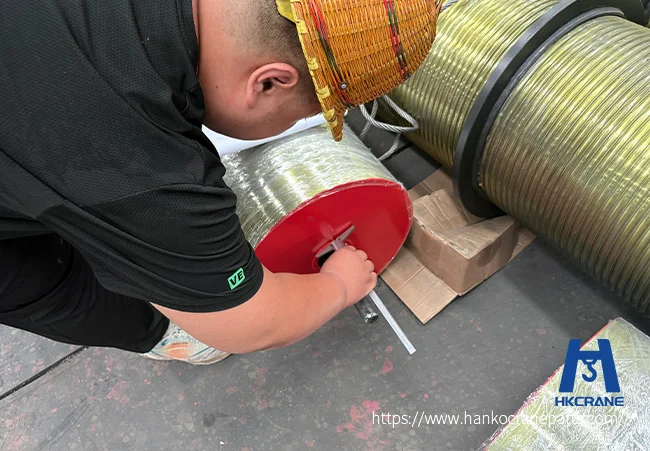
The drum bore connects to the drum shaft or is supported by trunnion journals on both ends. Journal diameter is determined by shaft strength and bearing selection. Common journal diameters range from 50 mm for small drums to 250+ mm for heavy-duty applications.
Standard Crane Drum Dimension Ranges
| Crane Capacity (t) | Typical Rope Diameter (mm) | Drum Diameter D (mm) | Barrel Length L (mm) | Shell Thickness δ (mm) |
|---|---|---|---|---|
| 5 | 12–14 | 250–350 | 400–600 | 12–16 |
| 10 | 14–16 | 300–400 | 500–800 | 14–18 |
| 16 | 16–18 | 350–450 | 600–1000 | 16–20 |
| 20 | 18–20 | 400–500 | 800–1200 | 18–22 |
| 32 | 20–24 | 500–650 | 1000–1500 | 20–25 |
| 50 | 24–28 | 600–800 | 1200–1800 | 22–28 |
| 80 | 28–32 | 700–1000 | 1500–2500 | 25–32 |
| 100+ | 32–40 | 900–1200+ | 2000–3500+ | 28–40+ |
These are general reference ranges. You must calculate actual crane drum dimensions for each specific application based on rope type, lifting height, speed, duty class, and safety factor.
Drum Groove Types
Spiral (Helical) Groove
The standard groove type for single-layer spooling. Rope follows a continuous helix from one flange to the other. Groove angle is typically 0.5°–1.5° per wrap.
Lebus (Parallel) Groove
Used for multi-layer spooling. The Lebus pattern features:
- Parallel grooves for approximately 75% of the drum circumference
- A cross-over zone for approximately 25% where the rope steps up to the next layer
- Consistent rope entry angle to prevent damage
If you use multi-layer drums without Lebus grooves, you will suffer from rope crushing, cross-overs, and premature failure. For more on groove design and rope matching, see our guide on wire rope drums performance.
Dimensional Tolerances
| Параметр | Standard Tolerance | Precision Tolerance |
|---|---|---|
| Drum diameter (machined) | ±1.5 mm | ±0.5 mm |
| Groove pitch | ±0.3 mm | ±0.15 mm |
| Groove depth | ±0.3 mm | ±0.15 mm |
| Barrel length | ±3 mm | ±1 mm |
| Flange runout (axial) | ≤ 1.0 mm | ≤ 0.3 mm |
| Drum runout (radial) | ≤ 0.5 mm | ≤ 0.2 mm |
| Surface roughness (groove) | Ra 3.2–6.3 µm | Ra 1.6–3.2 µm |
Crane Drum Dimension Calculation Checklist
Before you request a quotation or start manufacturing, prepare:
| Параметр | What to Provide |
|---|---|
| Rated load | Maximum lifting capacity of crane |
| Rope diameter | Wire rope outer diameter |
| Rope construction | 6×37, 6×19, IWRC, etc. |
| Lifting height | Maximum working height |
| Number of rope falls | Reeving ratio (1/1, 2/1, 4/1, etc.) |
| Drum diameter ratio (D/d) | Based on duty class |
| Spooling layers | Single or multi-layer |
| Groove type | Spiral or Lebus |
| Drum material | Cast iron, cast steel, or welded steel |
| Operating speed | Hoisting speed (m/min) |
| Duty class | FEM or ISO classification |
| Shell thickness calculation | If available |
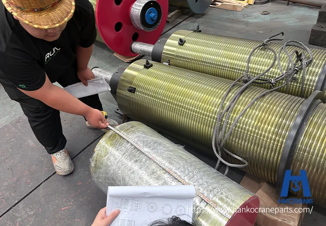
| Рисование | PDF or CAD for replacement drums |
When you provide complete crane drum dimensions and operating parameters, you ensure the drum is manufactured to the correct specifications and matches your existing rope and crane structure.
For a complete selection guide, see our crane drum selection article. For pricing factors, visit our crane drum price guide. To view our drum products, visit the Crane Drums product page.
Ready for a quotation? Send your crane drum specifications — rope diameter, lifting height, reeving ratio, and groove type — to Ханко. Our engineers will calculate the drum dimensions and provide a quotation with a manufacturing drawing within 24 hours.
ЧЗВ
How is crane drum diameter determined?
Crane drum diameter is determined by the D/d ratio, which is the drum diameter divided by the rope diameter. For standard industrial cranes, the ratio is typically 20–25. For heavy-duty cranes, the ratio increases to 25–30 to extend rope life. The minimum ratio is set by the crane’s duty class per FEM or ISO standards.
What is the groove pitch on a wire rope drum?
Groove pitch is the center-to-center distance between adjacent rope grooves. It equals the rope diameter plus 1–3 mm of clearance. For a 16 mm rope, the standard groove pitch is 17.5–18.0 mm per DIN 15061.
How do you calculate drum barrel length?
Drum barrel length equals the number of wraps multiplied by the groove pitch. The number of wraps is the total rope length divided by the circumference of the drum (π × D). For multi-layer drums, calculate each layer separately and account for the increasing diameter per layer.
What is a Lebus groove on a crane drum?
A Lebus groove is a parallel groove pattern used on multi-layer spooling drums. It features straight parallel grooves for most of the circumference and a cross-over zone where the rope transitions to the next layer. This prevents rope crushing and cross-overs that occur with plain helical grooves on multi-layer drums.
What is the difference between spiral and Lebus groove drums?
Spiral (helical) groove is the standard type for single-layer spooling, where the rope follows a continuous helix from one flange to the other. Lebus (parallel) groove is used for multi-layer spooling, featuring parallel grooves for most of the circumference and a cross-over zone where the rope steps up to the next layer. You should use Lebus grooves whenever you need 3 or more layers of rope on the drum.
What shell thickness do I need for my crane drum?
You can calculate the minimum shell thickness using the formula: δ ≥ (S × t) / (L × σ_allowable), where S is maximum rope tension, t is groove pitch, L is effective barrel length, and σ_allowable is the allowable compressive stress of your drum material. For welded steel (Q345B) drums, typical shell thickness ranges from 10–25 mm. For cast iron (HT200) drums, it ranges from 18–40 mm.
Does Hanko export crane drums to Russia and other target markets?
Yes. Hanko exports wire rope drums to Russia, Kazakhstan, Uzbekistan, Turkey, Brazil, and other target markets. You can request localized documentation, material certificates, and packaging suited to your country’s import requirements. Contact Hanko with your destination country for specific logistics support.
Does Hanko manufacture custom crane drum dimensions?
Yes. Hanko manufactures wire rope drums to custom dimensions including spiral and Lebus groove patterns. Provide your rope diameter, lifting height, reeving ratio, and duty class, and we will calculate and manufacture the drum to your specifications.
If you have drum drawings or specification sheets ready, send them to Hanko for a technical review and quotation. Hanko serves customers in Russia, Central Asia, the Middle East, Southeast Asia, South America, and other markets with complete export documentation.

 English
  Korean
  Russian
  Spanish
  Malay
Malay  Afrikaans
  Bulgarian
  French
  Bengali
  Italian
  Hungarian
  Vietnamese
  Thai
Thai  Indonesian
  German
  Arabic
  Japanese