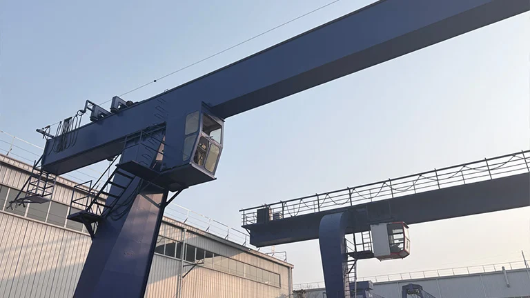
In a crane’s safe operating system, the brake is truly the “guardian of safety,” bearing the critical responsibilities of motion control, deceleration and braking, and preventing load slipping. Whether it is holding and positioning a suspended load during hoisting, ensuring smooth and stable stopping of the traveling mechanisms, or providing emergency braking in the event of a sudden failure, the performance of the brake directly determines the safety and reliability of crane operation.
Functions and Design Principles of Crane Brakes
During operation, a crane must frequently perform actions such as lifting, lowering, and traveling with heavy loads, and the core function of the brake is to precisely control these movements.
Specifically, its functions are mainly reflected in three aspects. The first is holding (support) braking: after the load reaches the required position, the brake reliably locks the mechanism and prevents the load from descending under the force of gravity. This function represents the most fundamental and critical role of a crane brake. The second is deceleration braking: during load lowering or mechanism operation, the brake applies braking torque to gradually reduce rotational speed until the mechanism stops smoothly, avoiding impacts caused by inertia. The third is emergency braking: when sudden faults such as overload or loss of control occur, the brake responds rapidly and forcibly stops the mechanism to prevent accident escalation.
Based on these functions, crane brake design follows the principles of safety and reliability, smooth braking, rapid response, and ease of maintenance. Among these principles, safety and reliability take top priority. The brake must provide sufficient braking torque and automatically engage under extreme conditions such as power or air supply failure, ensuring a fail-safe braking function. Smooth braking requires the brake to regulate braking torque steadily, avoiding impact loads during braking and protecting both the crane structure and the lifted load. Rapid response requires brake actuation delay to remain within a controlled range, ensuring timely operation in emergency situations. Ease of maintenance focuses on reducing long-term operating and maintenance costs while extending the service life of the brake.
Basic Components of Sistem Brek Crane
Although crane brake system are available in various types, their basic construction is generally the same. They mainly consist of five parts: the brake frame, brake shoes, brake wheel (or brake disc), actuating device, and auxiliary devices. These components work together to perform the braking function.
The brake frame serves as the fundamental supporting component. It mounts the brake shoes, actuating device, and other components, ensuring correct relative positioning during braking. Its structural strength directly affects braking stability, and manufacturers typically use cast iron or welded steel plates for construction. The brake shoes form the core friction components. Their linings must provide a high coefficient of friction along with good wear and heat resistance.
Due to environmental requirements, non-asbestos friction materials have become the mainstream, and some designs allow adjustment to compensate for wear. The brake wheel (or brake disc) works together with the brake shoes to generate braking torque. Manufacturers usually produce brake wheels from No. 45 steel, while brake discs offer better heat dissipation and perform better under harsh operating conditions. The actuating device functions as the execution core of the brake and falls into four main types: hydraulic, pneumatic, electromagnetic, and mechanical. Auxiliary devices include components for clearance adjustment, wear compensation, and limit control. These devices ensure stable brake operation and help extend service life.
Main Types of Crane Brakes
According to different braking methods, commonly used crane brakes can be classified into electro-hydraulic drum brakes, electro-hydraulic disc brakes, safety brakes, wind-proof brake.
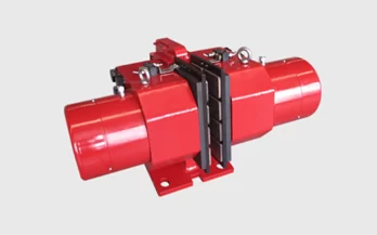
Electro-hydraulic drum brakes
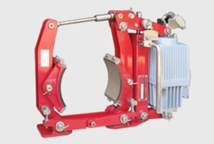
The YW series electro-hydraulic drum brakes are widely used for deceleration and holding braking in crane and conveying equipment, port handling systems, metallurgical equipment, mining machinery, and construction machinery.
This series offers a wide range of models, covering specifications from YW-160 to YW-800, compatible with brake wheel diameters of 160–800 mm. The braking torque ranges from 80 to 10,000 N·m, enabling it to meet the braking requirements of different load conditions.
|
YW and YWB Series Drum Brakes |
|
| Product Model | YW(B)160-220、YW(B)200-220、YW(B)200-300、YW(B)250-220、YW(B)250-300、YW(B)250-500、YW(B)315-300、YW(B)315-500、YW(B)315-800、YW(B)400-500、YW(B)400-800、YW(B)400-1250、YW(B)500-800、YW(B)500-1250、YW(B)500-2000、YW(B)630-1250、YW(B)630-2000、YW(B)630-3000、YW(B)710-2000、YW(B)710-3000、YW(B)800-3000 |
| Brake Disc Diameter (mm) | 160、200、250、315、400、500、630、710、800 |
| Braking Torque (N·m) | 80~10000 |
Electro-hydraulic disc brakes
The YP series electro-hydraulic disc brakes are high-performance, multi-functional advanced products. Thanks to features such as automatic equalization of pad retraction clearance and automatic compensation for lining wear, they are very convenient to maintain during operation.
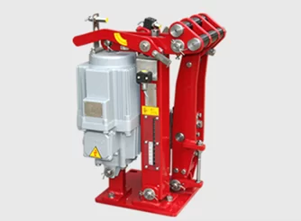
By adding various limit switches, the brakes can provide the necessary interlocking and protection signals to the main machine’s PLC. They are especially suitable for deceleration and holding (parking) braking of various mechanisms in modern large-scale specialized handling equipment, crane and conveying machinery, metallurgical equipment, mining equipment, and construction machinery.
| Specification | Thruster Model | Brake Disc Diameter (mm) | Maximum Braking Torque (N·m) |
| YP1 series | Ed220-50、Ed300-50、Ed500-60、Ed800-60 | 315、355、400、450、500 | 280~1750 |
| YP2 series | Ed500-60、Ed800-60、Ed1250-60、Ed2000-60、Ed3000-60 | 450、500、560、630、710 | 1000~8400 |
| YP3 series | Ed1250-80、Ed2000-80、Ed1250-60、Ed3000-80 | 630、710、800、900、1000、1250 | 3750~20000 |
Safety Brake
The SB series hydraulic safety (emergency) brakes are high-power braking devices designed for use on low-speed shafts (drum shafts). They are widely applied for emergency safety braking on the low-speed shafts of hoisting and luffing mechanisms in medium and large cranes, as well as port handling machinery.
They are also suitable for service braking and emergency safety braking of mining hoists, winches, and high-power inclined belt conveyors; safety braking of drive mechanisms for cable cars and cable cranes; and safety (emergency) braking on the low-speed shafts of hoisting mechanisms in special-purpose cranes such as casting cranes.
|
SB Series Safety Brake |
|
| Product Model | SB50、SB100、SB160、SB250、SB315、SB400、SB500 |
| Applicable Brake Disc Diameter (mm) | 500、600、1200、1800 |
| Brake Disc Thickness (mm) | 30、36、40 |
| Clamping Force F (kN)) | 50~500 |
Wind-Proof Brake
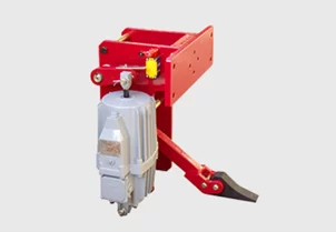
The YXZ series electric-hydraulic wind-proof wedge brake is mainly used for wind protection during operation and as auxiliary wind-prevention braking when idle for large and medium-sized outdoor cranes and port handling equipment.
|
YXZ series electric-hydraulic wind-proof wedge brake |
|
| Product Model | YXZ-250/80、YXZ-350/80、YXZ-400/80、YXZ-440/80、YXZ-500/80、YXZ-550/80、YXZ-600/80、YXZ-630/80、YXZ-700/80、YXZ-710/80、YXZ-800/80 |
| Brake Wheel Diameter (mm) | 250、350、400、440、500、550、600、630、700、710、800 |
Working Process of Crane Brakes
Optimized version:
The operation of a crane brake assembly closely coordinates with the movement of the mechanism. Taking the hoisting mechanism as an example, the working process of a crane hoist brake can be divided into four stages: lifting, hovering, lowering, and emergency braking. The control system strictly follows the principle of “release the brake before starting; stop first, then apply the brake” to ensure safe equipment operation.
Lifting Stage:
After the operator issues a lifting command, the control system first energizes the brake actuator (such as an electromagnetic coil or hydraulic station) to release the brake. Once the brake fully releases, the hoisting motor starts and drives the load upward through the transmission shaft, wire rope, and hook. During lifting, the brake remains released to allow normal mechanism operation.
Hovering Stage:
When the load reaches the target position, the operator issues a stop command. The control system first stops the hoisting motor. After the motor speed drops to a safe range, the system cuts off the power or air supply to the brake actuator. Under spring force, the brake engages and locks the transmission shaft, reliably holding the load in position. At this stage, the brake must withstand the full load torque.
Lowering Stage:
When the operator issues a lowering command, the control system first releases the brake and then reverses the hoisting motor to lower the load. During lowering, the control system continuously monitors motor speed and descent speed. If overspeed occurs, the system automatically adjusts the braking torque to ensure smooth and controlled load descent.
Emergency Braking Stage:
In the event of sudden faults such as overload, motor runaway, or wire rope failure, the control system immediately activates emergency braking. It rapidly cuts off power or air supply to the brake actuator, allowing the brake to engage quickly under spring force and force the hoisting mechanism to stop. At the same time, safety devices such as overload limiters issue alarms to alert the operator to address the fault.
In addition, the control system continuously monitors brake status. If it detects faults such as failure to release, excessive brake clearance, or severe lining wear, the system triggers an alarm and prevents further operation of the mechanism.
Key Factors Affecting the Working Performance of Crane Brakes
The working performance of crane brakes is influenced by multiple factors, primarily including braking torque, brake clearance, friction coefficient of the brake lining, heat dissipation performance, and the performance of the actuator.
Braking Torque:
The braking torque must be designed according to the crane’s service class, rated lifting capacity, and operating speed, ensuring it exceeds the maximum torque of the mechanism. Insufficient braking torque can lead to brake failure, while excessive torque may cause impact during braking, damaging mechanism components. Therefore, regular inspection of the braking torque is necessary to ensure it meets the design requirements.
Brake Clearance:
Brake clearance refers to the gap between the brake shoe and the brake wheel (or brake disc). Excessive clearance can cause delayed braking and insufficient torque, while too little clearance can create additional friction between the brake shoe and wheel/disc, increasing energy consumption and accelerating lining wear. Regular adjustment of brake clearance is required to maintain it within a reasonable range.
Friction Coefficient of Brake Lining:
The friction coefficient is a key factor determining braking torque. A higher friction coefficient generates greater torque under the same pressure. If the friction coefficient decreases due to wear or contamination (e.g., oil, dust), braking torque will be insufficient, affecting braking performance. Therefore, the condition of brake linings should be regularly checked, and worn or contaminated linings should be replaced promptly.
Heat Dissipation Performance:
During braking, friction between the brake shoe and wheel/disc generates significant heat. Poor heat dissipation can cause the brake lining to overheat and carbonize, reducing the friction coefficient and potentially leading to “thermal fade,” which compromises braking performance. Therefore, it is essential to ensure that the heat dissipation channels of the brake wheel or disc are unobstructed to prevent high-temperature-induced brake failure.
Performance of the Actuator:
The actuator (such as electromagnetic coils, hydraulic stations, or pneumatic systems) directly affects the brake’s response speed and reliability. Malfunctions in the actuator (e.g., burned-out coil, insufficient hydraulic pressure, air leakage in cylinders) can prevent the brake from releasing or engaging properly, affecting crane operation. Regular inspection and timely maintenance of the actuator are necessary to ensure reliable brake operation.
In crane operations, safety comes first, and a reliable brake serves as the core barrier protecting it. Hanko Heavy Industry’s crane brakes, featuring high-strength, wear-resistant brake linings and precise transmission structures, are compatible with a full range of cranes, including bridge, gantry, and tower types, easily handling demanding conditions such as heavy-load starts and stops and high-altitude hovering. With a modular design, fast response, and stable braking torque, they effectively eliminate risks such as hook slippage and brake failure. For any inquiries, please feel free to contact us.