With the rapid development of industrial automation, three-phase asynchronous variable-frequency motors have become standard equipment in many industries. This type of motor combines a three-phase asynchronous motor with variable-frequency drive (VFD) technology to achieve speed control. By adjusting the supply frequency of the stator, the motor changes its synchronous speed and regulates operating speed accordingly. Compared with conventional motors, variable-frequency drive induction motors feature a simple structure, convenient manufacturing, easy maintenance, stable performance, and reliable operation. As a result, they are widely used across industrial applications.
This article explains the working principle, key features, application fields, and selection considerations of three-phase asynchronous variable-frequency motors. It aims to help technicians, equipment purchasers, and operation and maintenance managers quickly understand the essentials of variable-frequency motor selection and application.
Working Principle
A variable frequency motor consists of three components: the motor body, the variable frequency drive for motor(VFD), and sensing/monitoring devices for feedback and protection.
-
Motor Structure and Electromagnetic Torque Generation
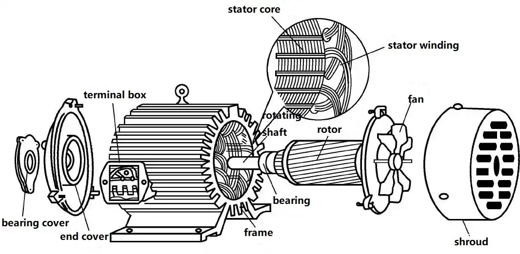
A three-phase induction motor mainly consists of a stator and a rotor. The rotor sits inside the stator and maintains a small, precisely controlled air gap between the two. The stator comprises the stator core, windings, and frame, while the rotor consists of the rotor core, windings, and shaft. Bearings and end covers support the rotor to ensure stable and smooth operation.
The rotor’s main function is to generate induced current under the stator’s rotating magnetic field, producing electromagnetic torque that converts electrical energy into mechanical energy. Based on rotor winding structure, induction motors are classified as squirrel-cage or wound-rotor types.
During operation, the rotating magnetic field induces current in the rotor windings, creating torque that drives the rotor to rotate in the same direction as the magnetic field. The rotor speed is always slightly lower than the magnetic field speed.
-
Variable Frequency Drive and Speed Control Principle
The frequency converter transforms fixed-frequency utility power into three-phase AC with adjustable frequency and amplitude. By altering the power supply frequency, it controls motor speed to achieve precise torque and power output.
- Voltage-frequency conversion speed control: Adjusts motor speed by modifying the supply voltage. The converter modulates output voltage frequency and amplitude based on control signals to match motor speed with the required speed.
- Frequency-based speed control: Adjusts the motor’s supply frequency to regulate speed. For example, converting the input voltage frequency from 50Hz to 30Hz reduces motor speed to 60% of the original.
By altering the input frequency and voltage supplied to the motor, the VFD enables smooth speed control, overcoming the limitations of traditional asynchronous motor speed regulation.
-
Closed-Loop Control and Speed Feedback System
To achieve precise speed regulation, variable frequency drive systems for three-phase motors typically use closed-loop control. In this configuration, engineers install position sensors, such as encoders, on the motor shaft to feed the actual rotational speed back to the motor control system. The control system then compares the actual speed with the set speed and actively adjusts the inverter output. As a result, the system gradually reduces the speed error and brings the actual speed closer to the target value, ensuring accurate and stable speed regulation.
Product Features
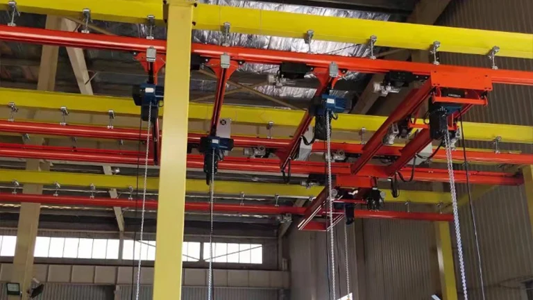
- Resistance to Mechanical Vibration and Impact: Reinforced motor structure to withstand mechanical vibrations and impacts encountered during crane operation.
- Higher Thermal Insulation Rating: Incorporates a higher thermal insulation rating to accommodate heat generated during operation.
- Frequent Starting, Stopping, and Reversing: Designed to withstand the effects of frequent starting, stopping, and reversing operations required for crane motors.
- Rotor design: To minimize inertia during starts and stops, rotors are typically designed with a slender profile, reducing start-up time and minimizing start-up losses.
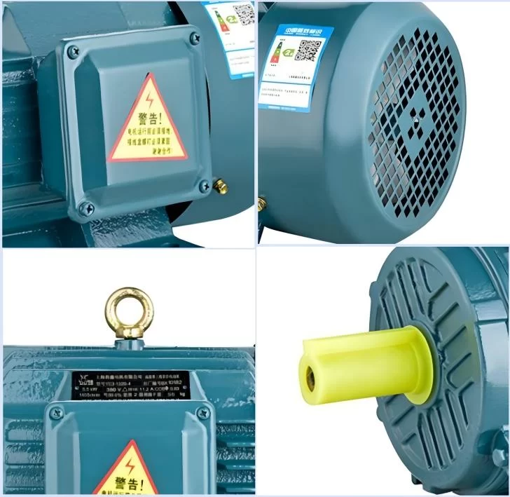
- Protective covers and sealed design: To withstand dusty working environments, the motor’s protective housing and sealed construction are key features.
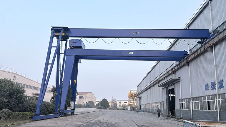
Application Fields
Three-phase asynchronous variable-frequency motors are widely used across multiple sectors and industries because they offer flexible speed regulation and adapt well to diverse operating conditions, including but not limited to:
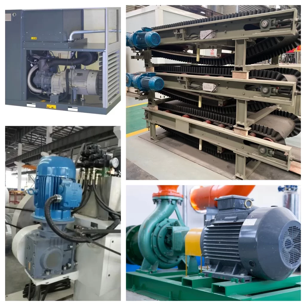
- Pump and Fan Applications: Equipment such as water pumps and centrifugal fans achieve precise speed control through variable frequency regulation, saving energy and enabling smooth starts.
- Compressors and Air Handling Equipment: Adjusting speed according to load demands in air compressors, refrigeration compressors, and similar equipment to enhance energy efficiency.
- Conveying Equipment: Precise control via variable frequency speed regulation for conveyors, elevators, etc., preventing excessive impact and damage to materials.
- Machine Tools and Equipment: Providing accurate machining control to improve processing quality and efficiency.
Selection Criteria
Here we focus on selecting variable frequency motors for metallurgical hoisting applications.
Motor Power Selection
Motor power. Comprehensive consideration must be given to various forces during lifting and operation. For hoisting mechanisms, power is determined based on maximum load capacity and lifting speed. Travel mechanisms require consideration of travel speed, track friction, and potential gradient resistance.
Motor Speed Requirements
Motor Speed. Speed must align with operational requirements. Different work phases in metallurgical lifting equipment demand varying speeds: lifting mechanisms require low, stable speeds for precise hoisting, while traveling mechanisms select speeds based on distance and time constraints. Additionally, consider the motor’s speed regulation range, which should match actual operational speed variations to ensure stable operation across all speeds.
Motor Duty Cycle and Operating Mode
Motor Duty Cycle. Metallurgical lifting equipment operates in complex environments with diverse working patterns, typically under intermittent cyclic duty or short-time duty. Under intermittent cyclic duty, the motor undergoes frequent starts, stops, and braking. This demands robust overload capacity and heat dissipation performance to withstand repeated load fluctuations. Short-time duty implies the motor must withstand significant loads for brief periods, necessitating the ability to deliver sufficient power without overheating or damage.
Motor Protection Rating (IP Class)
Motor protection rating. Metallurgical and lifting environments are harsh, potentially containing dust, moisture, and corrosive gases. Protection ratings are generally denoted by “IP” followed by a number, with higher numbers indicating better protection.
Motor Cooling Method
Motor cooling methods. Common cooling methods include self-cooling, air cooling, and water cooling. For smaller power ratings or relatively low ambient temperatures, self-cooling or air cooling may suffice. However, for high-power motors or those operating in high-temperature environments, water cooling provides more efficient heat dissipation, ensuring stable motor performance.
Motor Insulation Class
Motor insulation class. Different insulation classes correspond to different permissible operating temperature ranges. In high-temperature metallurgical environments, motors with higher insulation classes should be selected to maintain reliable insulation performance during prolonged high-temperature operation, preventing electrical failures caused by insulation degradation.
Motor Torque Characteristics
Motor torque characteristics. Metallurgical lifting equipment requires sufficient torque from the motor during start-up and braking. Particularly during the initial lifting of heavy loads, the motor must deliver substantial starting torque to ensure smooth hoisting. During braking, the motor’s braking torque must also meet the equipment’s rapid stopping requirements.
Why Choose Hanko Variable Frequency Motors?
High-Efficiency Motor Performance
Hanko Heavy Industry motors integrate advanced design concepts and proven technologies to deliver high energy efficiency under a wide range of operating loads. This helps reduce overall operating costs and improve long-term energy performance.
Quality, Stability, and Durability
We subject each motor to rigorous quality testing to ensure excellent stability and long service life. As a result, the motors operate reliably in harsh environments while reducing failure rates and maintenance costs.
Advanced Control Capability
Our motors support multiple control modes and respond quickly to dynamic operating conditions. This capability enables precise speed and torque control for complex and demanding industrial applications.
Environmental Compliance and Sustainability
Hanko Heavy Industry strictly follows international environmental standards. Our motors deliver high performance with minimal environmental impact, supporting global green manufacturing and sustainable development goals.
Wide Industry Applications
Our motors serve a broad range of industries and sectors. Whether used in industrial manufacturing, construction, or specialized applications, they provide dependable and adaptable drive solutions.
Comprehensive Variable Frequency Motor Solutions
We are committed to delivering reliable, efficient, and scalable variable frequency motor solutions. In addition to supplying high-quality motors, we offer complete system-level technical support throughout the project lifecycle.
End-to-End Technical Support
Our engineering services include operating condition analysis, simulation optimization, prototype validation, on-site installation, commissioning, and long-term maintenance. Together, these services form a closed-loop support system that ensures stable and predictable operation.
Project-Oriented Engineering Solutions
Whether you plan energy efficiency retrofits, capacity expansion upgrades, or new facility construction, our engineering team works closely with you to develop practical technical and economic solutions based on your actual operating conditions.
Long-Term Value for Customers
By combining advanced motor technology with professional engineering support, we help businesses achieve stable, safe, and energy-efficient production goals. Please feel free to contact us at any time for technical consultation or project support.